 How to add your sensor to the map
First of all, you should know that to withdraw public access should only be outdoor weather sensors and You are obliged to take measures to improve the reliability and accuracy of readings according to claim 2.3 of the Rules of the Project. There are no such requirements for private sensors.
1. Purchase from Project partners (or assemble yourself) a more convenient implementation of the monitoring device for collecting and transmitting readings to the server.
Examples of popular devices such as commercial and "collect yourself" is in Device catalog on the Project website.
2. Connect to your device pre-installed external sensors, turn on its power supply and connect to the Internet (e.g. through a home or office network), then configure the transmission of readings to the Project server at intervals of 5-60 minutes (for partners and commercial clients more often) according to the instructions from its developer.
3. Log in to the Project on its website or in the official app, specifying your e-mail or mobile phone number or use the social network of your choice.
4. In the section "Sensors" select the item "Add my device" and enter the alphanumeric serial number of your measuring device for registration in the project.
You should determine the ID of your device in the instructions for it or its firmware, if there are none, then contact the supplier. Registration of the device in the project is possible only after the successful transmission of the readings of its sensors to the server and the correctly specified ID. The device ID in the project has the same importance and uniqueness as the series and passport number for you.
5. Select the correct data type for each sensor: temperature, humidity, pressure, etc. If your sensor type is not in the list - specify "numeric" and its unit of measurement in "Sensors" on the Project website.
6. Specify names for the device and each of the sensors connected to it. Address in the name do not need to specify, there is a special field.
7. Bind to the map of the device, indicating the full address of its location (accurate to the house) or geocoordinates (for example, for a summer residence or a booth in the fields) by clicking on the "Address" line in the "Sensors" section. You can clarify the location by moving the marker of your device on the map by clicking "move" in its balloon on the map. By default, the server uses GeoIP, which is extremely inaccurate, especially for mobile operators.
8. If your Sensor is "outdoor" and complies with clause 2.3 of the Project Rules, then after 24 hours of uninterrupted operation, you can apply for its publication "for everyone" by clicking on the appropriate link in the line with this sensor in the site section Sensors \ Configuring.
9. If your Sensor does not meet the requirements of clause 2.3 of the Project Rules, but there is a need to share its readings with someone, then you can provide access to it to other project participants in the Sensors \ Configuring section of the site by clicking on the "Share" link in the line with with this sensor.
 Connecting Raspberry Pi to the Project
Raspberry Pi can also be used to transmit readings to the project server. Listed below are links to some of the methods of removal of indications with the help of a Raspberry Pi with a view to their long-distance transmission to the server of the project according to the transmission protocol of the sensors readings.
- Working with Public Monitoring in Python with Raspberry Pi / Habr
- Sending temperature data from TL-MR3020 and Raspberry Pi router to "people monitoring" / Habr
- Connect the wireless radiation dosimeter to the "Public monitoring" service via Raspberry PI / Habr
- The History of the interaction of "teapot" by DS18B20 and Raspberry Pi send data to the narodmon.ru / Habr
Questions, comments and additions - write to admin @ narodmon.ru
 Connecting Oregon weather stations to the Project
Weather stations and external sensors from Oregon can also be used to transmit readings to the Project server.
The following is an example of the implementation of transmitting readings to narodmon.com from the Oregon Scientific WMR88 weather station using the service Meteoplug or < a href="http://www.meteobridge.com/wiki/index.php/Home">Meteobridge.
1. The TP-Link TL-MR3020 router (or compatible) should already fully work with the Meteoplug or Meteobridge service. Those. You must already have registered, entered data about your weather station and all sensors connected to it according to the instructions on the Meteoplug or Meteobridge websites.
There is no need to enable the Meteoplug Cloud Graphing module in the Meteobridge settings.
2. All that remains is to upload a script to the router once, which, according to the schedule, every 10 minutes will take the latest readings from the standard weather station sensors (they are accumulated in the router), will form new data from them in a new format and will send them to narodmon.com.
3. Connect to your router using PuTTY and run the commands:
# Go to the root of the disk
cd/
# Download the script
wget http://narodmon.com/apps/oregon-uni.sh
# Give the script execution rights
chmod 755 oregon-uni.sh
4. If the router works with the Meteoplug service, then you need to copy and paste the following lines into the command line and press Enter.
echo "0 0 * * * /etc/init.d/loggerd stop; echo -n > /tmp/run/meteohub/inetupload; /etc/init.d/loggerd start" >> /etc/crontabs/root
echo "*/10 * * * * /oregon-uni.sh" >> /etc/crontabs/root
The first line at midnight restarts the data acquisition program and truncates the data file, otherwise it will swell over time.
The second line runs our script every 10 minutes.
5. If the router works with the Meteobridge service, then you need to copy and paste the following lines into the command line and press Enter.
echo "0 0 * * * /etc/init.d/loggerd stop; /etc/init.d/loggerd start" >> /etc/crontabs/meteobridge
echo "*/10 * * * * /oregon-uni.sh" >> /etc/crontabs/meteobridge
The first line at midnight restarts the data collection program.
The second line runs our script every 10 minutes.
6. Additional information about Oregon weather stations and sensors:
- Flashing Meteobridge Firmware
- Arduino Weather Station (OREGON EDITION)
- Weather Station Data Logger / SourceForge
- Decoding the Oregon Scientific V2 protocol / JeeLabs
- Oregon Scientific USB Station Logger/Reader / Google Project Hosting
- Weather station with clock (half an hour) / Devicter.ru
- Arduino&Oregon or do-it-yourself weather station / Habr
- Choosing a digital thermometer/weather station with a wireless temperature sensor for outdoor and home / iXBT Conference
- Full step-by-step instructions for connecting Oregon THN132N
 Connecting Arduino devices to the Project
For transmission of sensor readings can be used designs based on Arduino or Freeduino. Listed below are links to some variants of implementation of removal of the sensor readings and transmitting them to the project server according to the transmission protocol.
- A simple example of obtaining and sending temperature to narodmon.com / ESP8266
- Arduino Weather Station (OREGON EDITION)
- Monitoring the temperature in the hive at Wemos D1
- Weather station clock (half an hour) / Devicter.ru
-
- A bunch of UNO+EFcom v1.2+Public monitoring / Arduino.ru
- Send data via GPRS to the service "Public monitoring" / JT5.ru
- Control of humidity and temperature the home and beyond DIY / Star-t-hinking
- Weather home wireless weather sensor from Arduino Pro Mini / MYSKU.ru
- Connecting an Arduino to Russian project of Public monitoring / Student-proger.ru
- Barometric Pressure Sensor Module for Arduino or how to make a weather station with your own hands / MYSKU.ru
- The weather station on the Arduino and the MR3020 for the Public monitoring / cxem.net
- Connect Arduino Pro Mini + Enc28j60 + DHT11 + DS18B20 to the service narodmon.com / @imarh.ru
 Connecting Misol, WeatherSmart weather stations to the Project
To send data from a weather station, it must support selecting a custom server to send data to Weather Logger.
In the Weather Network \ Weather Station Settings section you specify:
Remote Server: Customized
Server IP/Hostname: narodmon.com (or eu.narodmon.com)
Server Port: 80
Server Type: PHP
Station ID: Specifies a unique MAC (serial number) that should be entered when registering a station in the project.
Password: can be left blank.
Tested on Conrad firmware 2.1.9 and 2.2.5.
Important! To avoid blocking, the transmission interval should be set to 5 minutes (default 1 minute) or pay to reduce the interval in the project.
Additional Information:
- Conrad firmware
- Buy on Aliexpress
- Description of the IpObserver station
 Connecting an air quality monitoring station to the Project
The station was developed in Germany and is assembled using instructions from sensor.community (formerly luftdaten.info).
Station components:
- microcomputer NodeMCU v3 CH340;
- fine dust sensor SDS011 or PMS5003;
- temperature, humidity, pressure sensor BME280;
- electrical box and tube 6x8 mm;
- Dupont connecting wires (female-female);
- flat USB-microUSB cable (2m or 3m);
- USB power supply with a current of at least 500 mA.
Device firmware:
- Download and run the program for flashing the Flashing Tool processor by selecting the version for your OS in the Assets section;
- select the required firmware from the list, for example latest_BME280_en.bin which contains Russified firmware for the BME280 sensor;
- connect NodeMCU to the computer using a short microUSB cable and check (or specify yourself) the connection port;
- click the Upload button and wait for the firmware download process to complete;
- unplug the NodeMCU from the USB port and plug it in again to reboot it.
Initial setup:
- from a PC or smartphone, connect to the airRohr-******* WiFi network
- in the browser, type the address 192.168.4.1
- in the firmware web interface, specify the settings for connecting to your home/work WiFi network;
- make sure that all necessary sensors are selected and active in the settings;
- in the APIs section, enable sending to InfluxDB:
Server: narodmon.com (or eu.narodmon.com)
Path: /post
Port: 80
User and password: can be left blank
Click Save and Reload.
- to register in the Project as a device ID/MAC, enter “esp8266-*******” where instead of ******* the device ID is indicated in the firmware settings (above).
 Connecting weather stations AMBWeather, EasyWeather to the Project
In the built-in web interface of the stations, enter the following:
Hostname: narodmon.com (or eu.narodmon.com)
Path: /post
Port: 80
Upload Interval: 300
Then save the settings and reboot the station.
To register a station in a project, use the value of the PASSKEY parameter.
Tested on station models WS2350 and WS-2902.
 How to debug (check for errors and activity) data from the device
In the process of developing new devices, it is often necessary to debug its Protocol for transmitting readings in order to detect and correct errors in it, but what if the limit of devices in the project does not allow you to do this ?
1. If your device is located in your home/office network and therefore has the same public IP address as your browser, you can use the Profile \ Data from my IP section of the website for debugging (after authorization) or use a short link narodmon.com/ip
2. If you are debugging a device connected to the mobile Internet (i.e. its public IP does not match your browser), you can use a link like this: narodmon.com/dev/DEVICEMAC
* Replace DEVICEMAC on your device's MAC (without : and -) in any case. If the device is already registered in the project, then read item 3 below.
3. For successfully registered devices, the debugging information can be found in section of the website Sensors \ Configure \ data received from the device.
4. If during the debugging process your IP was banned by the server, you can check it and unban it using the /chkban IP and /unban IP commands in the @narodmon20bot Telegram bot. However, if the error is not fixed, you will be banned again.
PS The debug information contains data about all data packets received by the server in the last couple of hours from your device, as well as errors in its Protocol (if any). If this data is not available, then either the IP / MAC of the device differs from the one you specified, or the device does not have Internet access (incorrectly configured or not paid for).
 How to protect the sensor from overheating (Rules 2.3)
It is no secret that the most popular and popular public weather sensors in the Project are temperature, so the Project increases the limit of private devices to its owner for quality data from street thermal sensors.
However, a significant number of thermal sensors are placed in violation of clause 2.3 of the Project Rules, which leads to the withdrawal of their public status and, as a result, a decrease in the limit of devices.
We list the main methods of protection sensors from overheating:
1. The Sensor should be placed on the shadow side of the building, most often it is the north side. You can use inexpensive wifi devices or 10-20m twisted pair to connect 1-wire DS18B20 sensors.
2. Protect the sensor from direct sunlight and precipitation with an opaque visor or canopy.
3. Install the sensor at least 20 cm away from the building wall, for example, using a rod. This factor is especially critical during the winter season in heated buildings.
4. The sensor should be free to blow through with outside air. This should not be forgotten by those who like to place the sensor inside plastic containers, as without free air circulation, the greenhouse effect is obtained.
5. It is not recommended to use humidity and pressure sensors not intended for outdoor use of the DHT/SHT/AM/BMP series, as they either quickly fail due to excess humidity or show a slightly elevated temperature due to their own little heating.
The most suitable in all parameters design for the placement of temperature sensors is called a meteorological Stevenson booth. In the Internet there are many options for this design, incl. and on our website among the photos in the rating of public sensors.
 Power supplies and 99% error in humidity sensors
If you use very common hygrometers and they constantly show 99% humidity, then this article is for you.
It turned out that the sensors are very sensitive to the quality of the power supply, ripples with a range of 150-200 millivolts completely paralyze the humidity channel, while the temperature channel and the bus exchange work normally and the checksums match. And since today many radio amateurs use ready-made power supplies worth 100 rubles, you should not be surprised that their quality is very lame. And power supply from the USB port of a computer is also often not ideal. Most all-digital devices don't get in the way, though. And it also happens that the new power supply unit works fine, and after a week there is noise and the sensor connected to it starts to lie.
So, if your sensor constantly shows 99% and is powered by a voltage of 5 volts, then try first to replace the power supply with a known normal one. Unfortunately, you may have to go through several different power supplies, preferably from different manufacturers. However, a good power supply unit will not cost 100 rubles, and it may simply not be at hand. As a very simple solution, you can simply try to put a 270-560 Ohm resistor in the break of the sensor power wire (the wire going to the Vcc contact).
This works, since the current consumed by the sensor is very small, only 3 milliamperes, then this resistor will not “drain” the power much, and the stabilizer already in the sensor will still lower the voltage to three volts. At the same time, together with the capacitor already present in the sensor, this resistor forms a completely effective RC filter.
Well, some pictures:
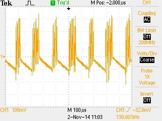
Let's take an average power supply unit - a charger. The label says 5V 1000mA.
This is how the noise coming to the Vcc sensor leg from this power supply looks like.

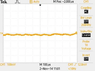
And this is how the picture looks after installing the resistor and, accordingly, the sensor began to work.

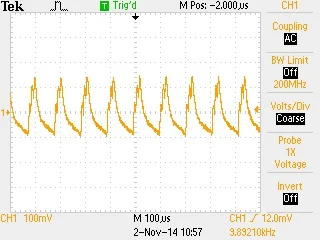
A picture from another power supply unit with a proud inscription 5V 1000mA. With this power supply, the sensor also shows 99%.

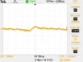
And here is a picture from the power supply that comes with the MR3020 router.
This is also an inexpensive power supply, but as you can see, there is little noise and the sensor works great with it without any alterations.

In general, be careful when choosing a power supply :) Good luck!
Source: etrivia.ru/news/O-vybore-bloka-pitaniya.